Tiếng Việt


CALYPSO
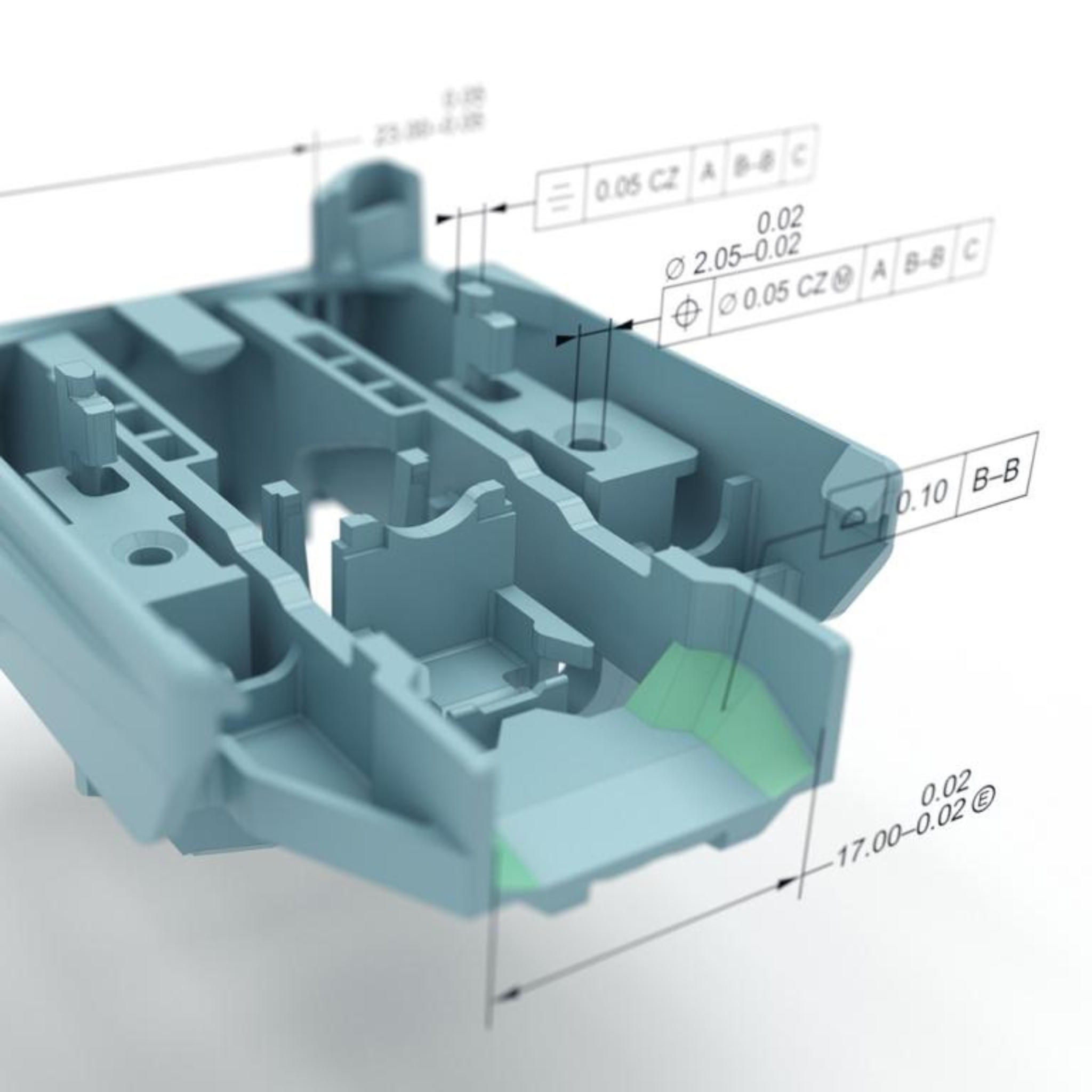
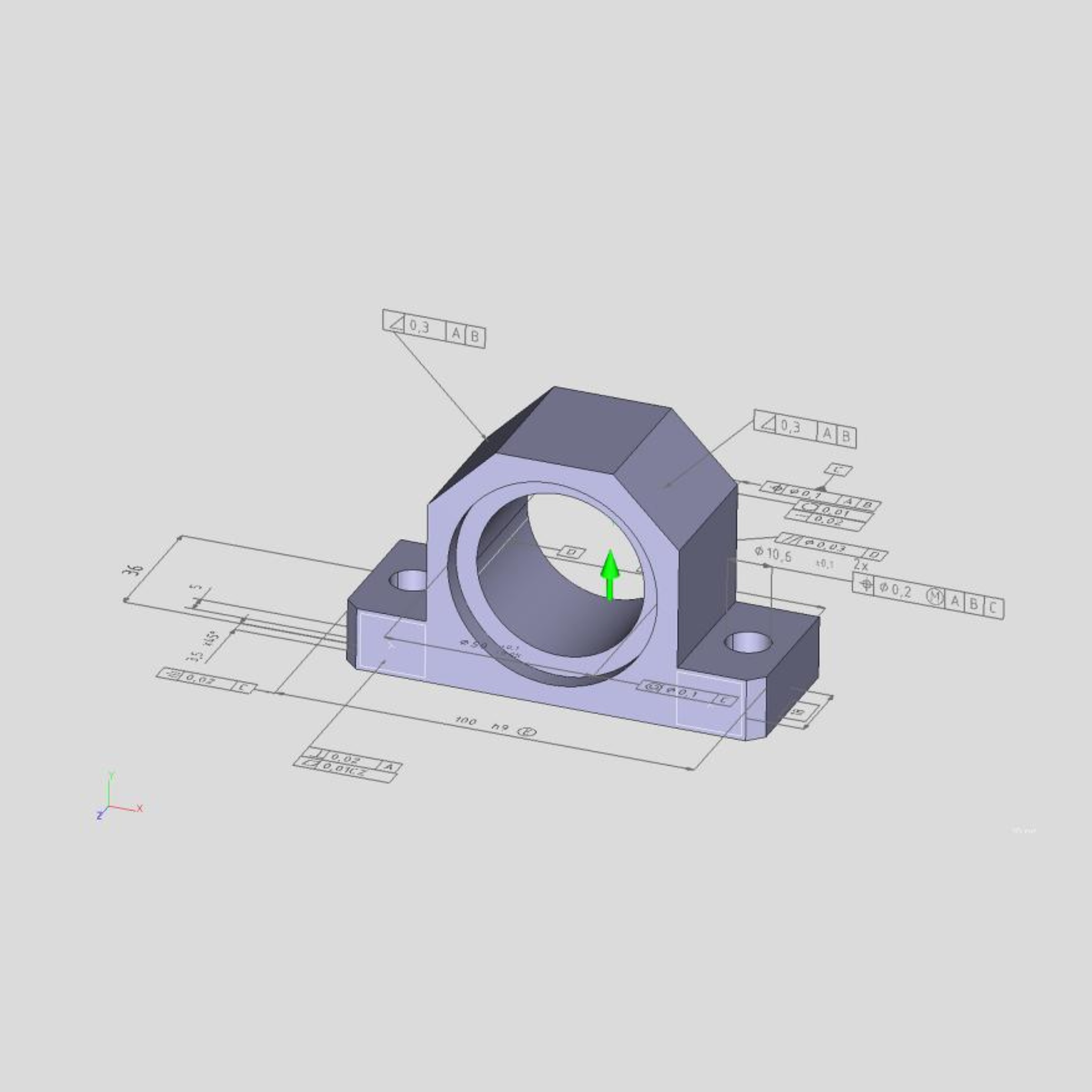
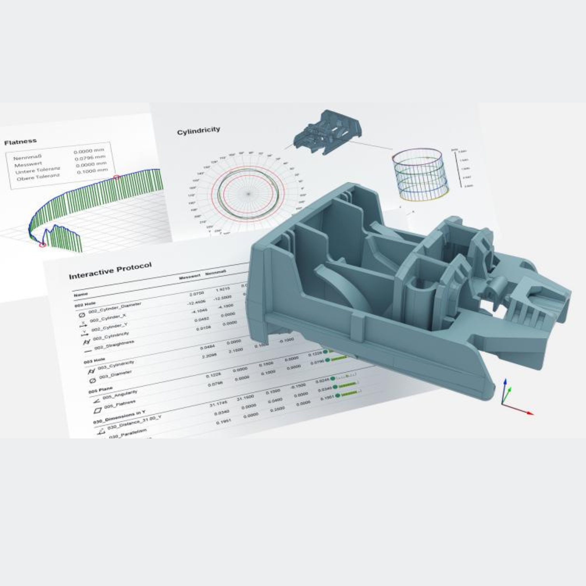
Calypso is one of the most highly rated coordinate measuring machine software applications in the world. The CAD kernel ensures unmatched operability, combined with the powerful features of the software designed to give you the highest flexibility and performance.
Improved AI Function (Internationally Patented)
The AI function includes three algorithms for automatic element recognition, automatic coordinate system setting, and automatic measurement plane recognition while assisting the operator. The AI function not only supports points, lines, flat surfaces, spheres, symmetry points, circles, and cylinders, but also supports cones, ellipticals, square holes, and long holes without having to select the element type before measuring. The simple operating procedure allows for successive measurements from measuring one of the elements at random points to pressing the “End” button to stop the element measurements.
• Automatic geometric element recognition
Our own measurement method and identification algorithm (patented in Japan and overseas) enables automatic recognition of geometric forms by direct measurement (probe) of the workpiece. This significantly reduces the procedures for input measurement items.
• Automatic coordinate system recognition
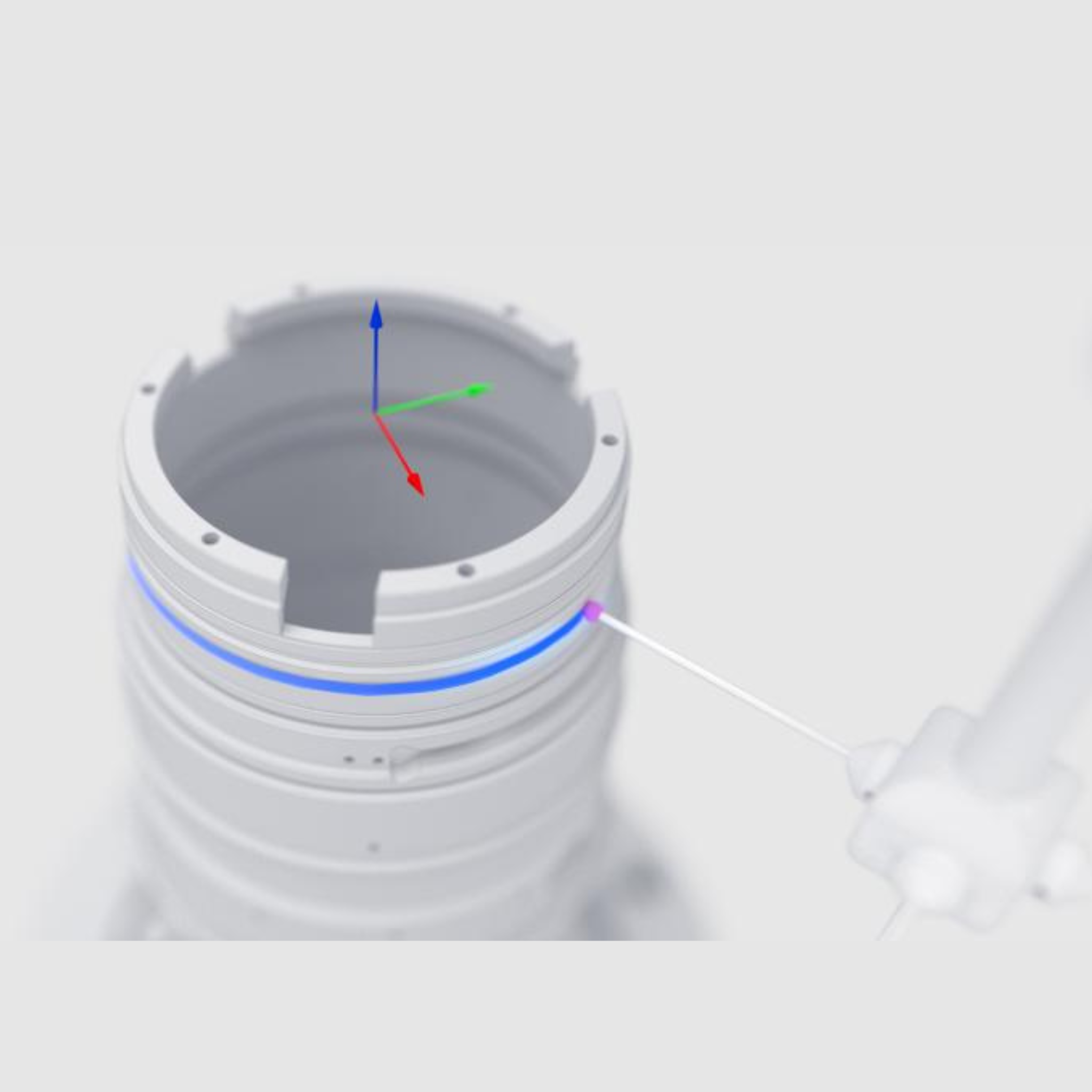
The geometric elements are measured and the items required for the coordinate system settings (spatial compensation, rotation compensation, root) are determined automatically and these settings are configured.
Automatically create gauge lines
Calypso’s safe plane philosophy eliminates the need to enter probe path points (intermediate points). When the bypass boundaries (the area around the workpiece) are defined, the probe will automatically move on a safe plane so that it does not interfere with the workpiece. For movement on the same surface, a different safety plane can be configured to make the amount of movement smaller.
The gauge line is automatically generated in accordance with the safety plane, the additional safety plane, the number of measurement points, and the distance back to the probe. The gauge and probe points can be arbitrarily specified within and between the measuring elements, which allows the operator to create the most appropriate gauge line.
On-screen probe angle simulator (For articulated probes)
The operator may wonder if the probe is correctly oriented after specifying a direction such as axis A: 0° and axis B: -90°. The on-screen probe angle simulator provides a screen image of the probe set at the input and tilt angles, so the operator can confirm that the desired results have been achieved.
When CAD data is available, clicking on an element will automatically change the ideal probe orientation based on normal information. This function is especially useful in the case of tilt holes and tilt shafts.
Even without CAD data, the orientation of the probe can automatically change to the normal orientation relative to the actual projection plane being measured.
The operator used to enter the angle of rotation while inspecting the workpiece and planning to consider the interference of the stylus. With the on-screen probe angle simulator, setting the angle of rotation is simpler than ever.
The stylus simulation function option is required.